MIDIbox64E Extension: 4x20 LED-Matrix
by Ralf SuckowThis modification of the MIDIbox64E project allows to randomly control a matrix of 80 LEDS using 24 digital outputs of the MIDIbox DOUT module. In my case, the LEDs are 16 RGB LEDs illuminating a 4x4 button matrix, and 4 additional peers of double-LEDs for a red-green crossfade selector function of the second row of the same button matrix. The RGB LEDs have one red, one green and two blue diodes each, so all in all its 80 LEDs. The matrix is part of a project to build an experimental controller for Ableton Live, where it serves as a multi-purpose clip launch pad and track control matrix.
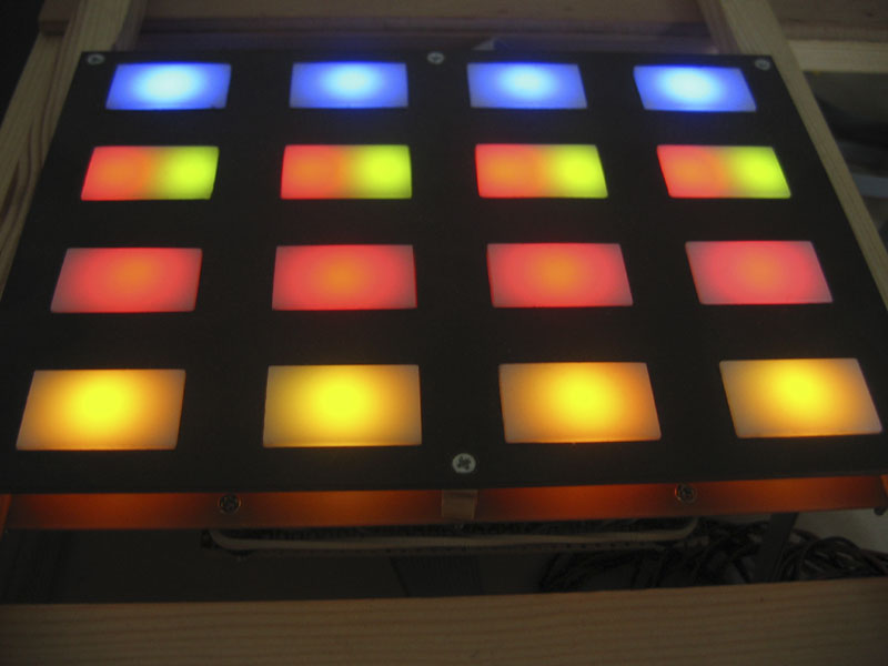
The figure below shows the 4x4 button matrix in its initial (power-on) state.
Here is the circuit diagram of the 4x20 LED matrix: LEDMATRIX4x20.pdf.
Compared to the well-known MIDIbox64E 16x16 LED rings, each of the LEDs is provided with a significantly higher average current, thus ensuring good color visibility at day even if all LEDs are turned on at the same time (the LEDs shine through white acrylic glass buttons, which further reduce the available light).
Another difference to the LED rings is that each of the button colors (i.e. each of the RGB LEDs and the RG-RG-Peers) is addressed as a single encoder value. So it is sufficient to set a single controller value for each button, making switching of colors of the whole 4x4 matrix fast without too much load on the MIDI interface. The numbers beside each of the LEDs in the circuit diagram are the respective encoder numbers. This code table shows the relation between encoders, LEDs and MIDI controllers which results from the given wiring and the software modifications described below.
Multicolor LED driving
The modification uses an average current of 9mA per lighting LED. Each of the four LEDs of same color, with their anodes connected to the common current limiting resistor, are driven in a 1:4 busy cycle. Thus, the maximum average current taken by the anodes from the DOUT output pin is 4*9=36mA. To support this current, 74HCT595N are used instead of the standard 74HC595. The frequency of the busy cycle is determined by the invocation frequency of the USER_SR_Service_Prepare interrupt routine of MIOS, which is approx. 250 Hz.
Each of the LED colors needs its own resistor value due to the different forward voltages. The values have been determined empirically to adjust the 36 mA current for four diodes in a row. The RGB LEDs used are those called "LED 5 rt/gn/bl-6" from www.segor.de. Their advantage is their large lighting angle, leading to a more even illumination of the buttons. They have two blue diodes, which allow for different lighter or darker colors, as well as an almost white color if all LEDs are on. The cathodes of red+blue and blue+green LEDs are put on separate pins, so all in all we have six pins.
The cathodes of all LEDs in a column are driven by a single DOUT pin during one of the four multiplexing phases. If all these 20 LEDs are turned on, they need a instantaneous current of 20*9=180mA, which even the 74HCT595 cannot supply. Thus, an additional ULN2003A is used as driver. It negates the DOUT cathode signal, compared to the 16x16 LED rings solution. So, the ULN2003 connects the cathodes to ground when it gets a +5V signal at its input. This makes the LEDs light. The software modifications take this into account.
Currently, the LED technology advances quickly, each month new RGB diodes get available. The new ones are brighter at the same current, cheaper, or have easier to handle packages. For example, the ones named "LL-509 RGBC2E-006" from Segor are quite nice, bright and less expensive than the used ones. If you use other diodes, make sure that they have separate anodes. Also ensure that the forward voltage of the LEDs (esp. the blue ones) is not higher than about 4V at 10 mA, else you'd not be able to drive them with the 5V DOUT pin, taking into account that the current from the cathode goes through the ULN2003 to ground, which also takes some 0.4V. And, you want some spare to regulate the current with the limiting resistor.
The software modifications
Some Software Modifications of the MIDIbox64E were necessary to drive the 4x20 LED matrix.
Pictures
The following selection of pictures illustrates the implementation process.

|

|

|

|

|

|

|

|

|

|

|

|

|

|
|

|

|

|
Kudos to ...
- Thorsten Klose from www.ucapps.de for the absolutely great MBHP/MIOS project, design and software.
- Duggle from midibox.org for explaining why MIDIbox64E works even if overloaded, and for the great hint to try ULN2003.
© 2005 Ralf Suckow. All rights reserved.